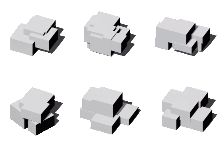
EvoMass | 进化体量
A computational building massing design generation and optimization tool that empowers designers to explore high-performing design prototypes during the pre-design and early stages.
Loading manual content... | 正在加载手册内容...
EvoMass User Guide 使用指引
This user guide is based on EvoMass 0.4.3. The original 0.4.1 version was published on 15 August 2024, and this guide was updated on 1 October 2026. Because EvoMass is under active development, some interface labels and screenshots may differ slightly between versions.
本指南基于EvoMass 0.4.3版本。最初的0.4.1版本于2024年8月15日发布,本指南于2026年10月1日更新。由于EvoMass仍在持续开发,不同版本中的界面名称和截图可能略有差异。
Contents
1.2. Start your first run of using EvoMass 开始使用
1.4. Learn how to use EvoMass 学习使用EvoMass
1.5. About this user guide 关于该指引
2. Design Generation Part 1 (Subtractive component) 设计生成1 (减法组件)
2.1.2. Subtractor (Voids) 削减体(负空间
2.1.3. Boundary Constraint 边界约束
2.1.5. Target Gross Area 目标建筑面积
2.2.2. Separation Control 分离控制
2.2.5. Remove Small Mass 去除细碎体量
2.2.7. Subtractor Appearing Position 削减体位置控制
2.3. Transformation Setting 变换设定
3. Design Generation Part 2 (Additive component) 设计生成2 (加法组件)
3.1.2. Additive Unit Mass 叠加子体量
3.1.4. Target Gross Area 目标建筑面积
3.2.2. Separation Control 分离控制
3.2.5. Vertical Constraint Check 垂直约束检查
3.2.7. Unit Masses Appearing Position 子体量位置约束
4.3.2. Scatter/Pareto Plot 散点/帕累托图
4.3.3. Improvement Viewer 改进解窗口
4.3.4. Information Viewer 信息窗口
4.5. Restart/Load Optimization 重新开始/载入优化
5.2.1 Building Separation 建筑分离
5.2.3 Conflict Resolution 冲突处理
1. General Overview 总括
EvoMass is an integrated tool for building-massing generation and optimization, primarily intended for performance-based architectural design. Rather than focusing solely on numerical optimization, EvoMass supports optimization-based design exploration: it helps designers extract information from the design space, understand the implications for building performance, and incorporate those insights into ideation and conceptual development.
EvoMass是一个用于建筑体量生成与优化的一体化工具,主要面向性能导向的建筑设计。与只关注数值优化的工具不同,EvoMass支持基于优化的设计探索:帮助设计师提取设计空间中的信息,理解设计对建筑性能的影响,并将这些认识融入设计构思与概念推敲过程。
EvoMass has two main functions: design generation and design optimization. Design generation is provided by two components that implement additive and subtractive form-generation principles and can produce diverse building-massing alternatives. Design optimization is provided by a hybrid evolutionary algorithm called SSIEA (steady-state island evolutionary algorithm). SSIEA uses an island-based population structure to preserve diversity while its steady-state replacement strategy accelerates the search.
EvoMass包含设计生成和设计优化两部分。设计生成部分提供两个分别基于“减法”和“加法”原则的建筑体量生成器,可生成具有差异性和多样性的体量方案。设计优化部分提供混合进化算法SSIEA(稳态多岛进化算法),通过多岛模型保持种群多样性,并通过稳态替换策略提高搜索效率。
Combining the design-generation and optimization components with simulation tools such as Ladybug Tools and ClimateStudio allows designers to define building forms and optimization objectives efficiently. The results provide a basis for identifying design patterns and understanding their implications for building performance.
将上述算法与Ladybug Tools、ClimateStudio等建筑性能模拟工具结合,可以帮助设计师快速定义设计生成与优化流程。优化结果可用于发现设计中的潜在特征和趋势,并作为考察和反思设计问题的依据。
1.1 Installation 安装
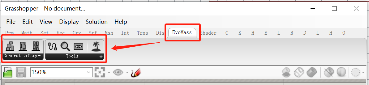
To install EvoMass, drag the GHA file onto the Grasshopper canvas, or replace the existing file in the component folder. If EvoMass does not appear on the Grasshopper tab, remember to unblock the GHA file as shown below.
安装EvoMass时,只需将相应的GHA文件拖入Grasshopper界面,或替换组件文件夹中的原有GHA文件。如果完成上述操作后工具栏中仍未出现EvoMass标签,请检查GHA文件是否被Windows阻止(右键单击GHA文件,打开“属性”,查看“常规”选项卡底部)。
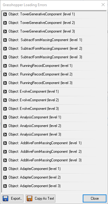
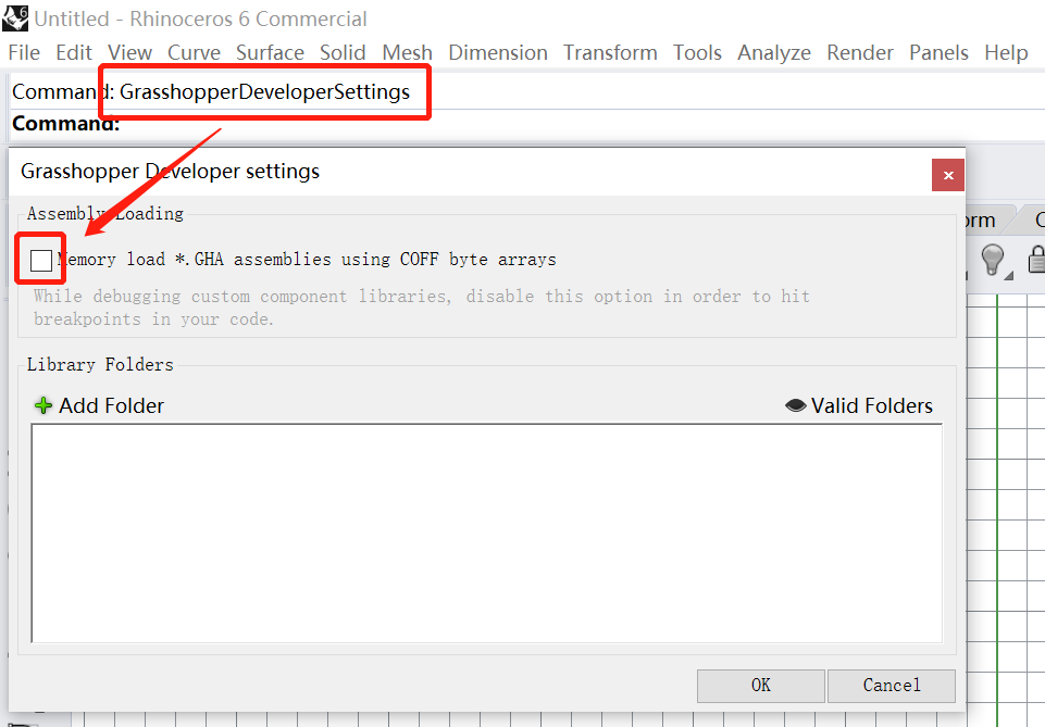
If a loading error appears when Rhino starts, type GrasshopperDeveloperSettings in the Rhino command line and disable the first option as shown below.
如果安装EvoMass后,出现了下图左中的加载错误,可以在Rhino中键入“GrasshopperDeveloperSettings”,并取消第一个选项(下图右)。
 |  |
|---|
1.2 Start your first run of using EvoMass 开始使用
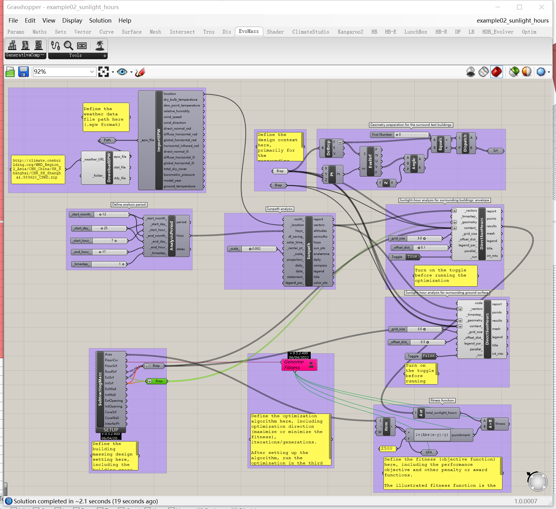
Getting started with EvoMass is straightforward. Several example files are included with the installation ZIP archive. Open an example as shown below, then follow the instructions to define the formal features of the generated building massing, the design context, the optimization objectives, and the SSIEA parameters. Ladybug Tools must be installed in Grasshopper before these examples can run.
为了帮助用户快速熟悉EvoMass,下载压缩包中提供了多个示例文件。打开示例文件(如下图),按照指引定义生成参数、设计环境和优化参数后即可运行优化。注意:运行这些示例前必须安装Ladybug Tools。
1.3 Activation 激活
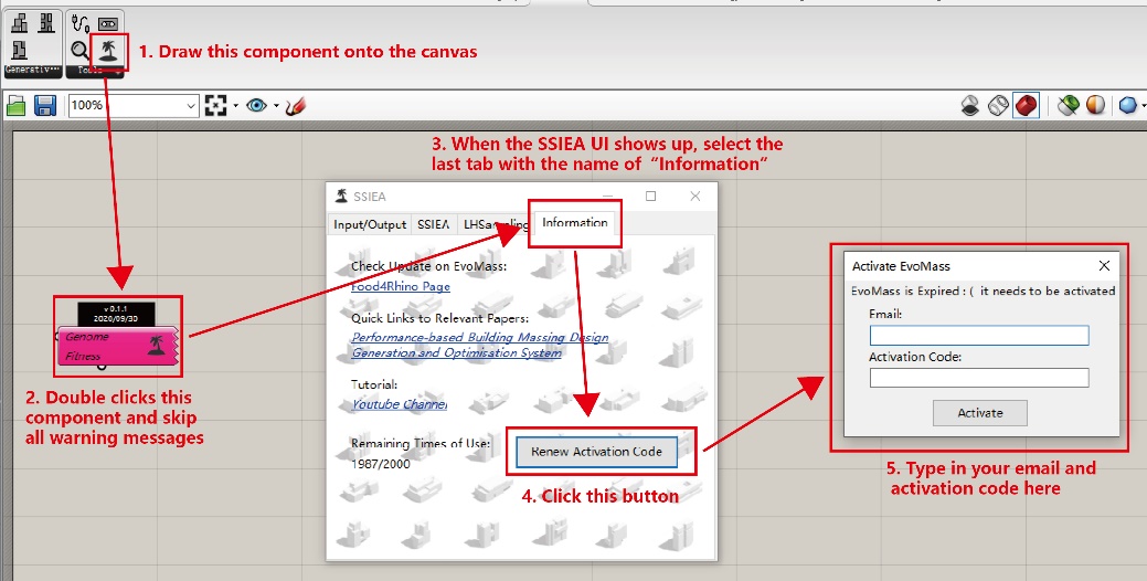
The first installation of EvoMass includes 200 run credits. To obtain additional credits, apply for an activation code. Activation-code applications are currently free and provide 10,000 additional runs. Apply using the Google Form or Tencent Form; the code will be sent to the email address provided. The image below shows the activation process.
首次安装EvoMass后会获得200次运行额度。之后需要申请激活码以获得更多额度。目前每次激活码申请可获得10000次额外运行额度。请通过以下链接申请激活码:Google Form 或 腾讯表格。激活码会发送到申请时填写的邮箱。下图展示了输入激活码的流程。
1.4 Learn how to use EvoMass 学习使用EvoMass
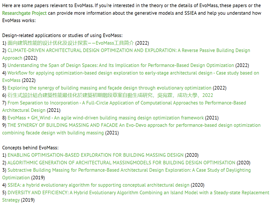
In addition to the included examples, tutorials are available on YouTube and Bilibili. Research papers on EvoMass are also listed on its Food4Rhino page (https://www.food4rhino.com/en/app/evomass). Reading these papers is recommended because EvoMass is intended not only to generate building forms, but also to support performance-based design exploration.
除随附示例外,YouTube 和 Bilibili 还提供了相关教程视频。Food4Rhino上也收录了与EvoMass相关的研究文章链接,可帮助用户进一步了解EvoMass在建筑设计中的应用潜力。
1.5 About this user guide 关于该指引
This user guide will take you walk through the major functions of EvoMass. Following this section, the two generative components are first elaborated, followed by the description of the evolutionary algorithm component (SSIEA).
本指南将介绍EvoMass的主要功能。接下来将依次介绍两个设计生成组件、设计优化组件以及建筑布局组件。
2 Design Generation Part 1 (Subtractive component) 设计生成1(减法组件)
The subtractive component implements a subtractive form-generation principle. It generates building massing by creating multiple voids within a predefined spatial volume. By defining the size and position of each void, you can shape the overall form of the building massing to suit your design intent. This section introduces the component's main functions.
减法组件以“减法”原则为核心,通过在一个预定义的体积中去除若干空间实现体量的生成。该组件可以通过对负空间的尺寸和位置进行控制,对生成体量的总体特征进行约束和干预,并以此满足不同的设计条件和意图。
2.1 Basic setting 基本设定
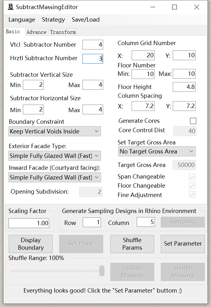
The basic settings panel of the subtractive component is shown below. Here you can define the main parameters that affect the generated form, including the initial volume, number of voids, and void-size constraints. Remember to click the Set Parameters button after you finish editing the values.
减法组件的基本设置面板如下图所示。该面板包含控制生成体量整体形态的主要参数,包括初始体量、负空间数量和尺寸等。完成输入后,单击“Set Parameters”以应用设计生成设置。
2.1.1 Initial Volume 初始体量
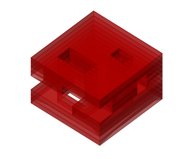
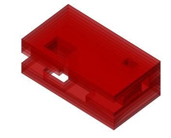
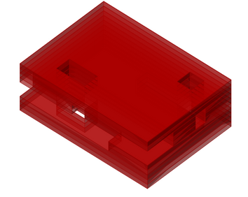
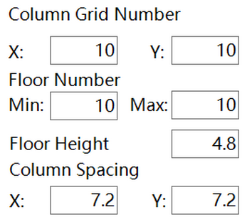
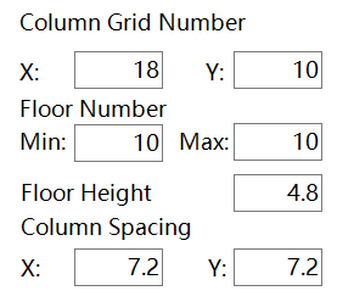
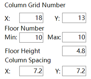
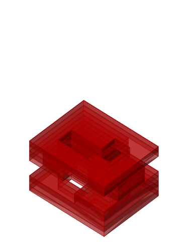
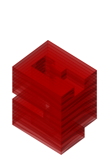
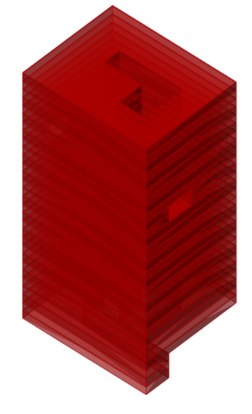
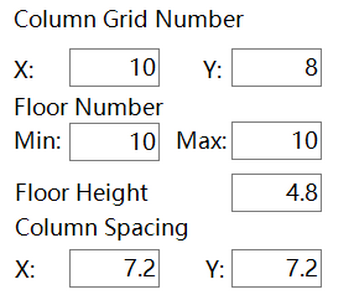
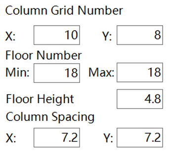
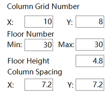
The initial volume defines the type of building massing to be generated, such as a high-rise tower or a mid-rise complex. Horizontally, the volume is defined by the column-grid counts and span sizes; vertically, it is defined by the number of floors and the floor height. You can also specify different span sizes in the two directions and a range of floor counts to increase design flexibility.
初始体量用于控制生成建筑的类型,例如高层塔楼或多层综合体。在该组件中,初始体量由进深、开间、层数、柱间距和层高共同控制。柱间距还可以在两个方向上分别设置,以提高形态灵活性。
 |  |  |
|---|---|---|
 |  |  |
 |  |  |
 |  |  |
2.1.2 Subtractor (Voids) 削减体(负空间)
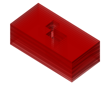
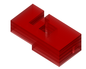
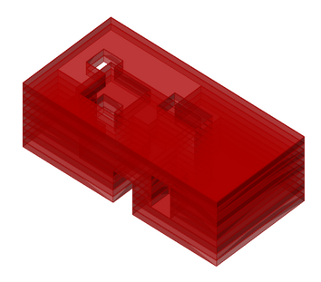
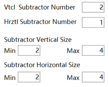
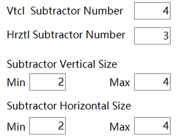
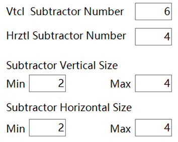
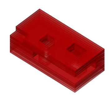
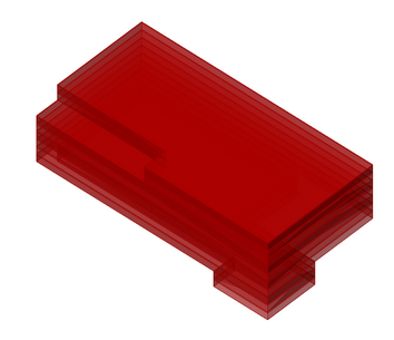
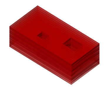
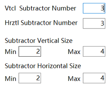
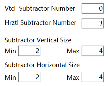
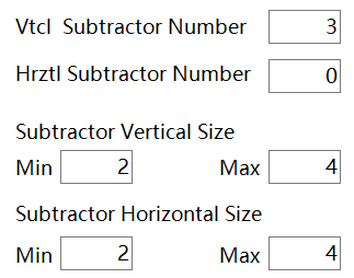
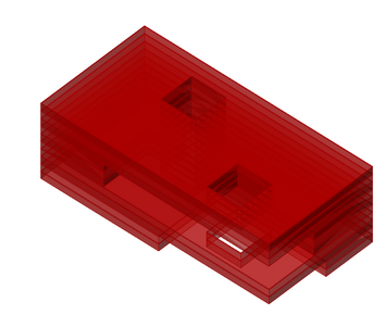
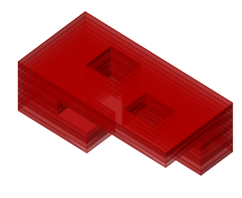
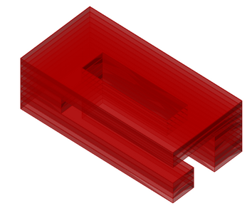
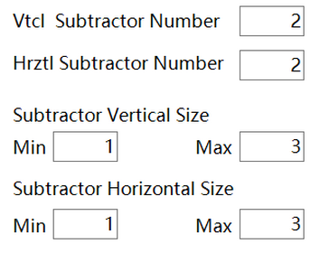
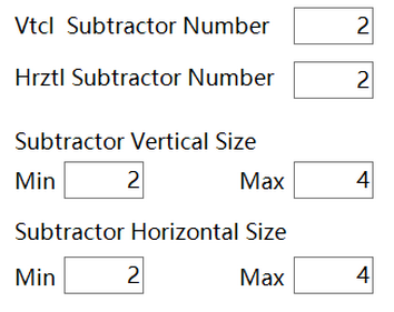
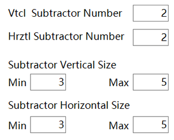
Subtractors create voids in the initial volume. Their number and size affect the complexity of the generated design. The component provides two types: horizontal subtractors, which can create stilts, void decks, and sky gardens; and vertical subtractors, which can create courtyards and atriums. Set the number of a subtractor type to 0 to disable that feature. The size controls the size of the resulting void.
削减体用于在初始体量中生成负空间。削减体的数量和尺寸会直接影响生成设计的复杂度。减法组件包含水平和垂直两种削减体:前者可生成架空空间、屋顶平台等水平向空间,后者主要用于生成中庭、庭院等垂直向空间。如果不希望生成某类空间,可将相应削减体的数量设为0。削减体的尺寸控制所生成负空间的大小。
 |  |  |
|---|---|---|
 |  |  |
 |  |  |
 |  |  |
 |  |  |
 |  |  |
2.1.3 Boundary Constraint 边界约束
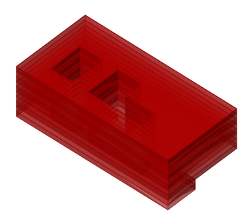
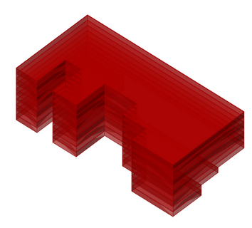
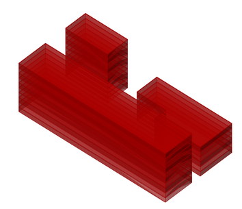
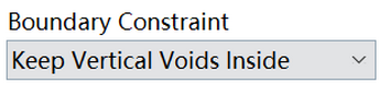
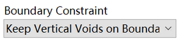
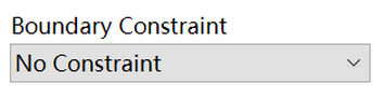
In the subtractive component, the boundary constraint controls the horizontal position of all vertical voids. It determines how those voids affect the overall form and whether the initial-volume boundary remains intact. The available modes are: keep all voids inside the volume, preserving the initial boundary; keep voids on the boundary, allowing L-shaped, U-shaped, or stepped footprints; and apply no constraint, allowing the building to be divided into two or three parts.
在减法组件中,边界约束用于控制所有垂直削减体的水平位置。该约束可以帮助设计师控制生成体量的可变范围,尤其是是否保留初始体量的边界。目前提供三种模式:第一种将所有垂直削减体保持在初始体量内部,从而保留初始边界;第二种将垂直削减体保持在初始体量边界处,可生成L形或U形平面;第三种不限制垂直削减体的位置,可生成更加自由的形体,例如彼此分离的体量。
 |  |  |
|---|---|---|
 |  |  |
2.1.4 Generate Cores 生成核心筒
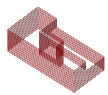
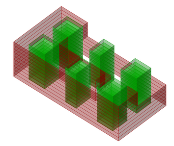
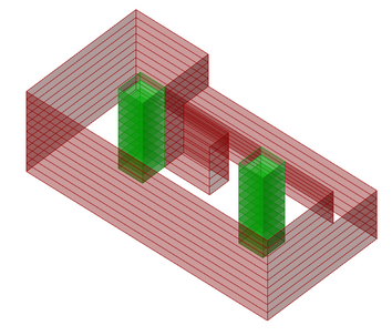
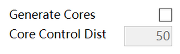
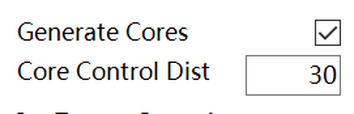
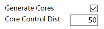
This function improves realism by inserting cores for structural or circulation purposes. The core affects nearby voids. The core control distance defines the distance from the core boundary to the building's external façade or corner.
该功能用于生成核心筒(用于交通或结构),使生成的设计更具实际参考价值。启用后,靠近核心筒的削减体会受到影响。核心筒的数量和位置会根据建筑平面尺寸以及与外墙的距离自动计算。
 |  |  |
|---|---|---|
 |  |  |
2.1.5 Target Gross Area 目标建筑面积
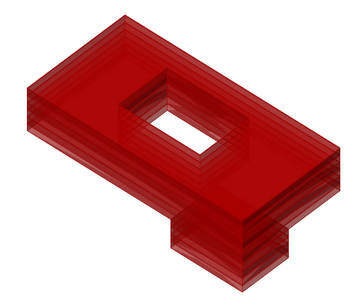
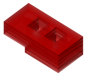
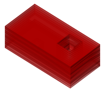
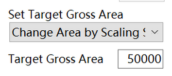
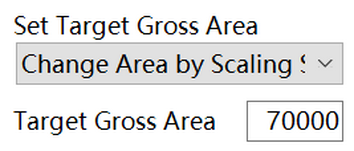
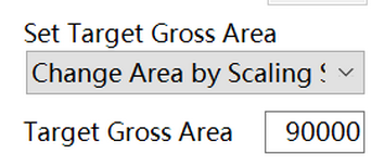
This function allows you to define the approximate building volume by specifying the gross floor area. Enabling it increases generation time. The component cannot guarantee that the target GFA will be achieved in all cases, particularly when it differs substantially from the basic volume.
该功能允许设计师通过建筑面积大致控制生成体量的规模。启用后,生成所需的计算时间会增加。请注意,该功能无法保证所有情况下都能得到接近目标建筑面积的设计,尤其是在基础体量与目标建筑面积相差较大时。
 |  |  |
|---|---|---|
 |  |  |
2.1.6 Façade Types 立面类型
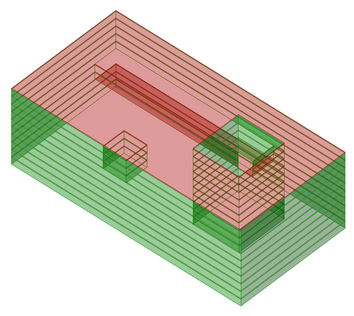
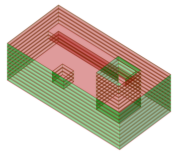
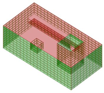
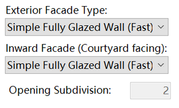
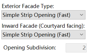
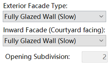
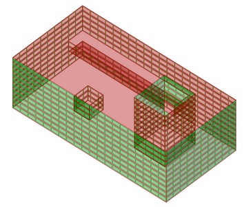
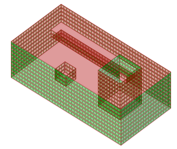
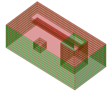
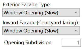
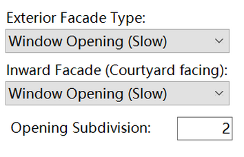
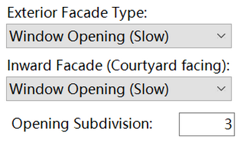
Different simulation tools may require different window geometries. The subtractive component provides four façade types: simple strip openings, simple fully glazed walls, window openings, and fully glazed walls. Choose the type appropriate for your project.
不同的性能模拟工具往往需要不同的输入立面类型,因此减法组件提供了四种不同的立面类型,包括连续条形窗、连续落地窗、点窗和玻璃幕墙。请根据性能模拟工具的要求进行选择。
 |  |  |
|---|---|---|
 |  |  |
 |  |  |
 |  |  |
2.2 Advanced settings 高级设定
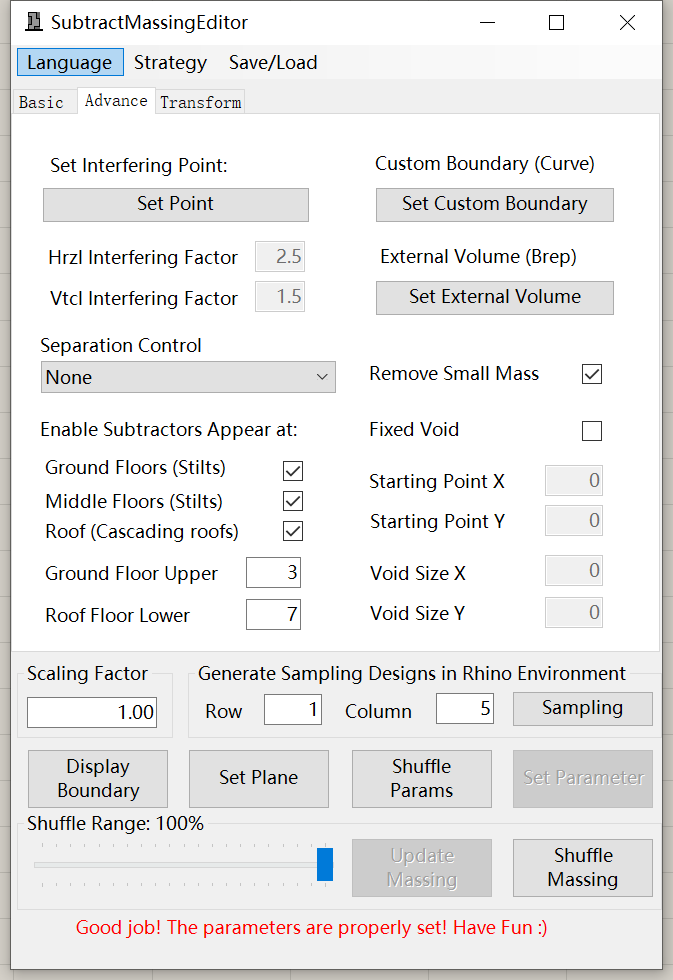
In the advanced settings, these parameters allow you to create more complex building-massing designs or guide the generation process more precisely. They are optional and can usually be left at their default values.
高级设置包含用于生成更复杂体量形态、并对生成过程进行更精细控制的参数。一般情况下无需修改这些参数。
2.2.1 Interfering point 干扰点
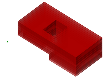
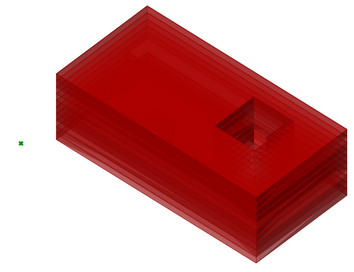
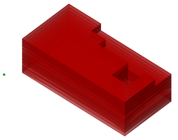
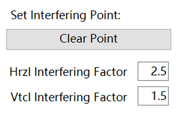
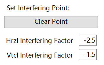
This function allows you to attract or repel voids relative to a point. For example, you can define an entrance area by attracting more voids toward it. Draw the point in Rhino, rather than Grasshopper, and pick it after clicking Set Point. Positive values indicate attraction; negative values indicate repulsion.
该功能允许设计师通过干扰点控制削减体的位置。例如,可以将削减体吸引到建筑的一侧或一角,以形成入口空间。使用该功能时,请先在Rhino中创建一个点,再单击“Set Point”进行拾取。正值表示吸引,负值表示排斥。
 |  |  |
|---|---|---|
 |  |  |
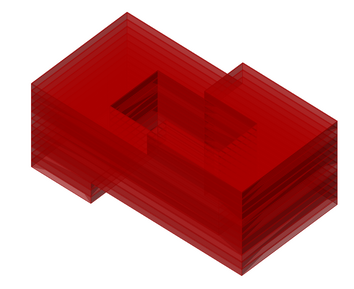
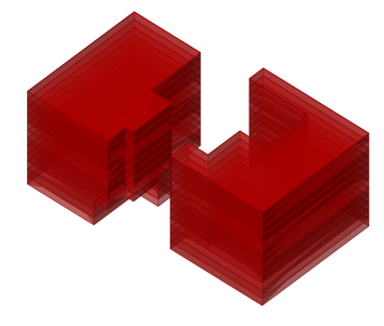
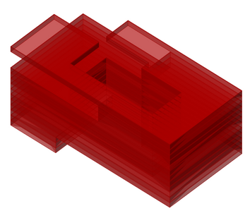
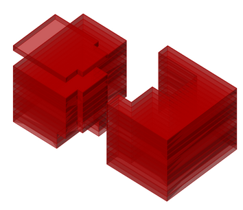
2.2.2 Separation Control 分离控制
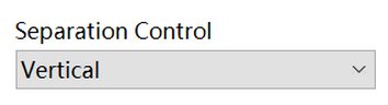
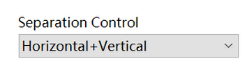
This function controls the spacing between voids. When enabled, it keeps voids farther apart in the horizontal and/or vertical directions.
该功能用于控制削减体之间的间距。启用后,彼此接近的削减体会在水平方向和/或垂直方向上保持更大的距离。
 |  |
|---|---|
 |  |
 |  |
 |  |
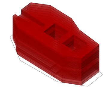
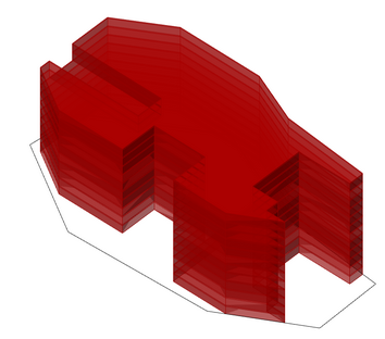
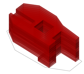
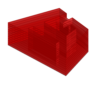
2.2.3 Custom Boundary 自定义边界
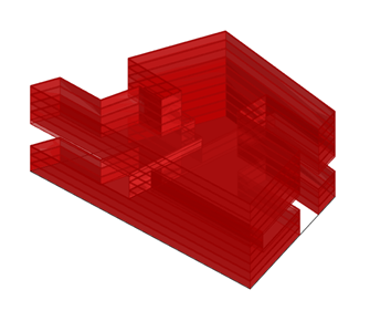
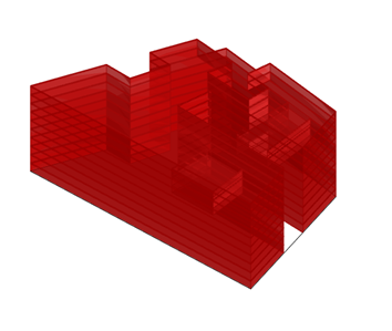
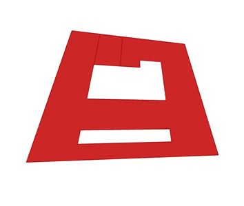
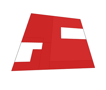
This function allows you to define a more complex building footprint by picking a closed polyline in Rhino. The boundary mode determines how the picked outline is used:
- Boundary Packing: the outline acts as a packing constraint. The generated grid and mass units are repositioned so that they fit within the custom boundary, while the original grid logic is retained.
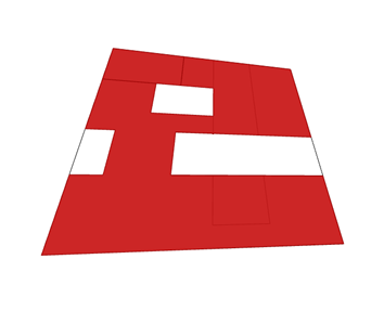
- Boundary Adaptation: the generated massing is mapped from the rectangular working footprint onto the custom outline, so the final footprint follows the selected boundary. This mode expects a closed quadrilateral whose area is reasonably close to the original footprint (within the component's validation tolerance).
该功能允许设计师在 Rhino 中拾取闭合的多段线,以定义更复杂的建筑平面边界。边界模式决定自定义轮廓的使用方式:
- 边界排布(Boundary Packing):将轮廓作为排布约束,在保留原有网格逻辑的基础上,重新调整生成的网格和体量单元,使其适合放入自定义边界内。
- 边界适配(Boundary Adaptation):先按矩形工作边界生成体量,再将其映射到自定义轮廓,使最终平面跟随所选边界。该模式要求边界为闭合四边形,且面积与原始工作边界相差不能超过组件的校验容差。
边界排布(Boundary Packing)
 |  |  |
|---|---|---|
| | |
边界适配(Boundary Adaptation)
 |  |  |
|---|---|---|
 |  |  |
| | |
2.2.4 External Volume 外部体量
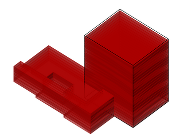
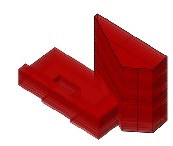
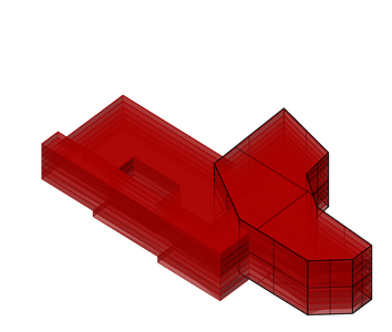
This function allows you to define an external fixed volume and combine it with the generated design. It is useful when only part of a building should vary—for example, keeping the tower fixed while varying the podium.
该功能允许设计师在设计生成中加入一个固定不变的外部体量。该功能可用于仅需要一部分建筑可变的设计条件下,如塔楼不变,裙房可变。
 |  |  |
|---|
2.2.5 Remove Small Mass 去除细碎体量
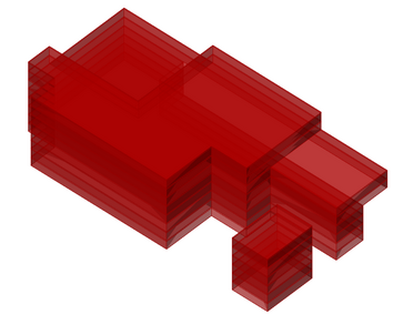
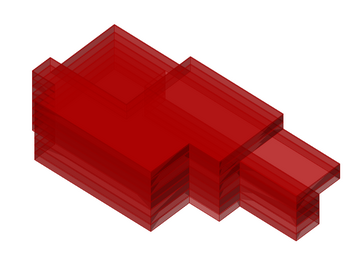
This function allows you to remove masses that are too small. This function is useful when there is a no-boundary-constraint or a keep-vertical-voids-on-boundary.
该功能会自动去除生成体量中过小的体量。它仅适用于“无约束”或“保持垂直空腔位于边界”的边界约束模式。
 |  |
|---|---|
 |  |
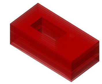
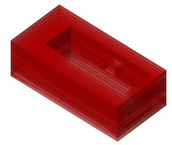
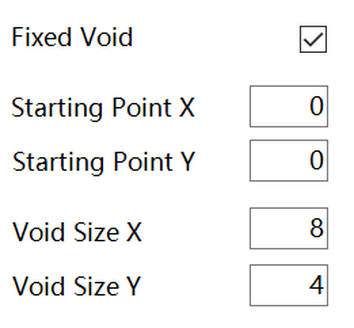
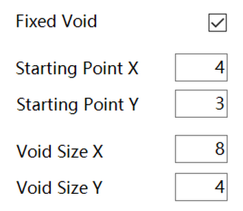
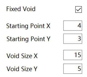
2.2.6 Fixed Void 固定负空间
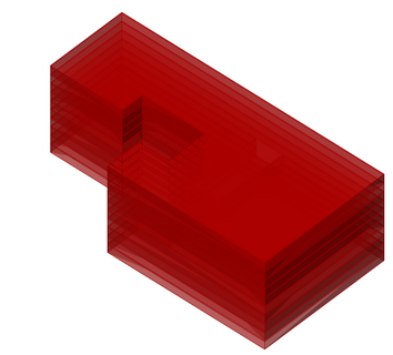
This function allows you to define a fixed void in the initial volume, such as a courtyard or an L-shaped footprint.
该功能用于在生成体量中加入固定的负空间,例如中庭或L形平面。
 |  |  |
|---|---|---|
 |  |  |
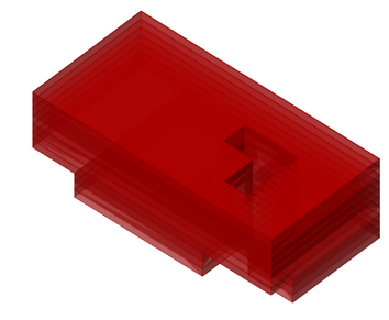
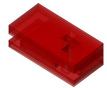
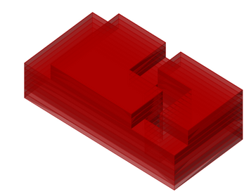
2.2.7 Subtractor Appearing Position 削减体位置控制
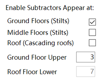
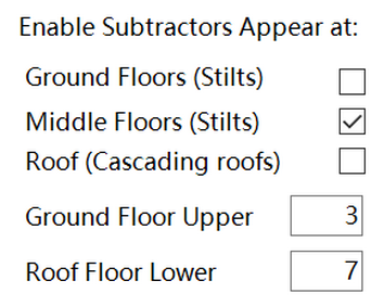
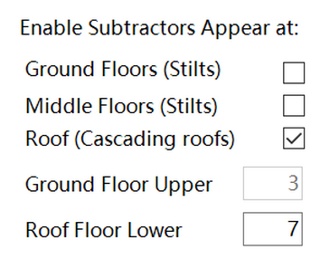
This function controls the vertical positions at which horizontal voids can be generated. It can be used to create more specific building types, such as buildings with stilts or cascading roofs.
该功能用于控制水平削减体在垂直方向上的位置,可进一步定义生成设计的特征,例如仅在底层生成架空空间或仅生成屋顶平台。
 |  |  |
|---|---|---|
 |  |  |
2.3 Transformation Setting 变换设定
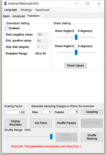
The Transformation tab contains functions for applying more complex morphological changes to the generated design.
此设置用于实现更复杂的形态变化。
2.3.1 Orientation 朝向
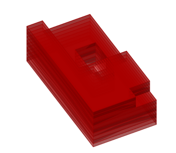
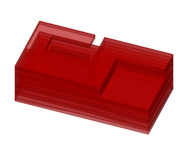
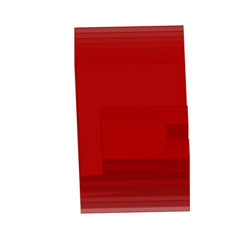
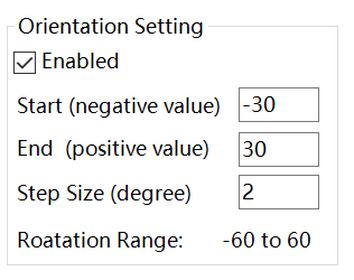
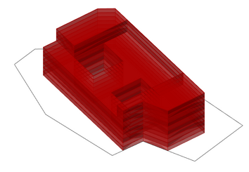
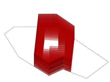
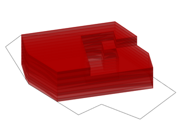
This function changes the building orientation by rotating it around its center point. “Start” and “End” are index values rather than direct angles; the rotation range is calculated as Start × Step Size to End × Step Size. For example, Start = -20, End = 15, and Step Size = 2 produce a range of -40° to 30°. The resulting range must remain between -90° and 90°.
该功能通过旋转体量改变建筑朝向。“Start”和“End”不是直接的角度值,旋转范围还会受到“Step Size”的影响,即范围为“Start × Step Size”至“End × Step Size”。例如,当Start为-20、End为15、Step Size为2时,旋转范围为-40至30度。旋转范围必须处于-90至90度之间。
 |  |  |
|---|---|---|
 | | |
This function is more useful when combined with the custom boundary. When you define a custom boundary, the design can create buildings with a fixed footprint but the void can face different directions.
该功能也可与自定义边界结合使用。定义自定义边界后,可以利用该功能探索不同朝向对建筑性能的影响。
 |  |  |
|---|---|---|
| | |
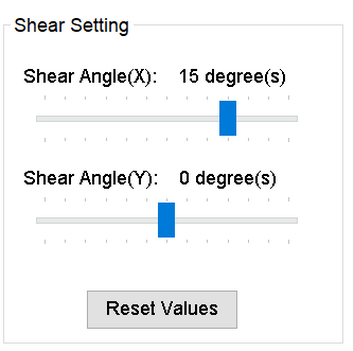
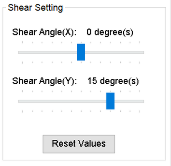
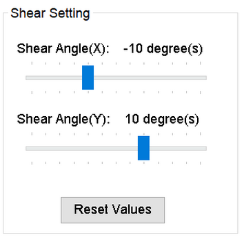
2.3.2 Shear 切变
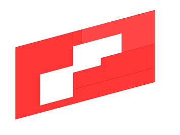
This function applies a shear transformation to the generated building design. The value set here remains fixed during optimization.
该功能可以对生成的建筑体量进行切变变换。请注意,所设定的切变角度在优化过程中不会改变。
 |  |  |
|---|---|---|
 |  |  |
2.4 Generation setting 生成设定
The Generation Settings control operations such as scaling the generated building, displaying the boundary, and setting the range of variation used when shuffling a design.
生成设置用于控制生成建筑,例如缩放建筑、显示边界以及控制设计变化范围。
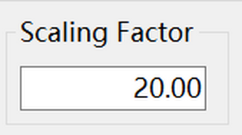
2.4.1 Scaling 缩放
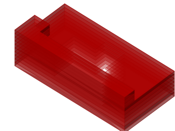
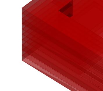
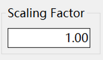
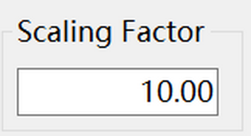
Due to different simulation tools that may use different unit systems, this function allows you to scale up the building geometry.
由于不同的性能模拟软件采用不同的单位,该功能帮助设计师快速对生成的建筑进行缩放。
 |  |  |
|---|---|---|
 |  |  |
2.4.2 Display Boundary 显示边界
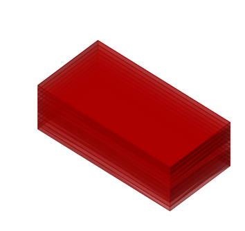
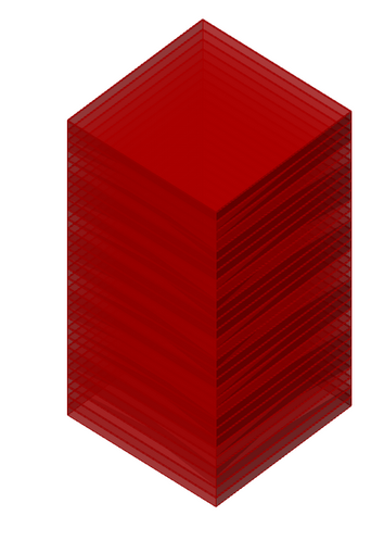
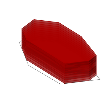
This function displays the maximum volume of the generated design, helping you detect collisions with surrounding buildings. It also works when a custom boundary is defined.
该功能用于检查初始体量和自定义边界是否正确,尤其是是否与周边场地建筑存在冲突(如交叠)。
 |  |  |
|---|---|---|
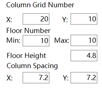 | 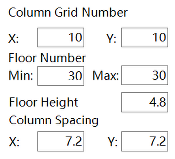 | |
2.4.3 Shuffle Range 随机变化范围
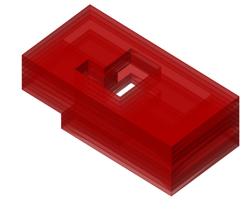
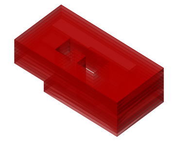
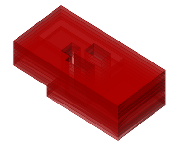
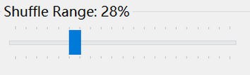
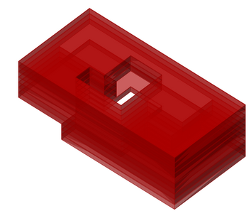
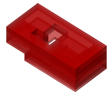
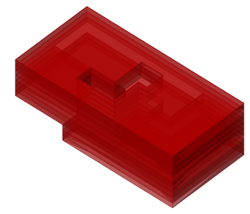
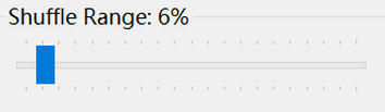
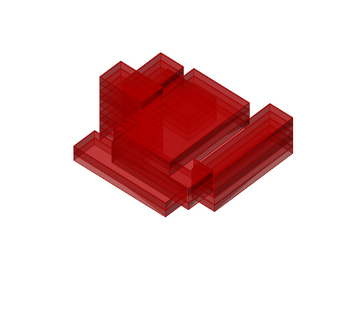
This function controls the variability applied when shuffling a design. It supports detailed exploration around an optimized design and helps you assess whether similar feasible alternatives exist. When the shuffle range is below 100%, the component restores the current design parameters before applying the variations. To use the shuffled design as the basis for further variation, click Update Massing.
该功能用于控制体量随机变化时的变化范围,支持围绕选定设计(通常是优化结果中得分较高的设计)进行进一步的细致探索。当该值小于100%时,组件会记录当前设计参数,并以其为基准进行调整。如需将随机变化后的设计作为新的基准,请单击“Update Massing”。
 |  |  |
|---|---|---|
 | | |
 |  |  |
 | | |
2.4.4 Save/Load 保存/载入
This function saves the current settings as an external file that can be loaded by another *.gh file or computer. It makes settings easier to restore, share, and reuse in other projects.
该功能可以将现有参数设置(基本设置、高级设置和变换设置)保存为外部文件,并由其他GH文件中的相应组件(减法组件)载入,便于保存、共享和在其他项目中复用生成参数。
3 Design Generation Part 2 (Additive component) 设计生成2 (加法组件)
The additive component implements an additive form-generation principle. It generates building massing by aggregating multiple unit masses within a predefined spatial boundary. By defining the size and position of the unit masses, you can shape the overall building form to suit your design intent. This section introduces the component's main functions.
加法组件以“加法”原则为核心,通过在一个预定义的空间边界中叠加若干子体量实现体量的生成。该组件可以通过对子体量的尺寸和位置进行控制,对生成体量的总体特征进行约束和干预,并以此满足不同的设计条件和意图。
3.1 Basic setting 基本设定
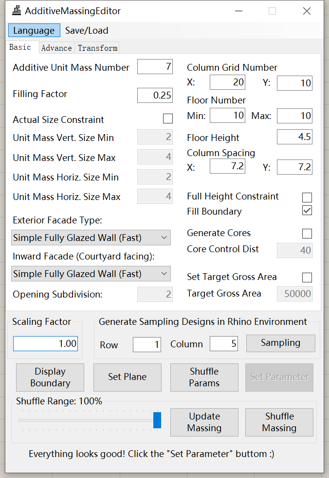
The basic settings panel of the additive component is shown below. Here you can define the main parameters that affect the generated form, including the spatial boundary, number of unit masses, and unit-mass size constraints. Remember to click the Set Parameters button after you finish editing the values.
加法组件的基本设置面板如下图所示。该面板包含控制生成体量整体形态的主要参数,包括预定义空间边界、子体量数量和尺寸等。完成输入后,单击“Set Parameters”以应用设计生成设置。
3.1.1 Spatial Boundary 空间边界
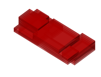
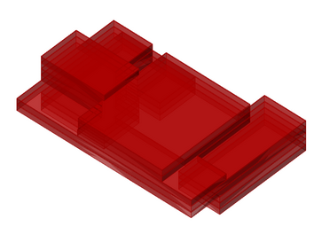
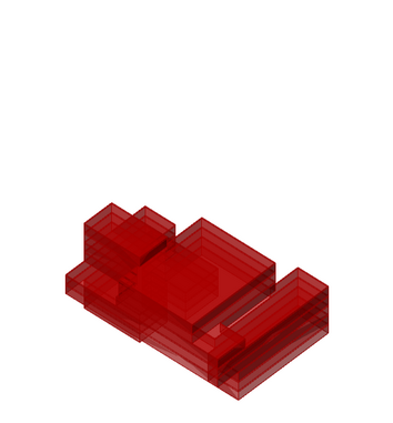
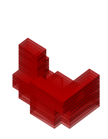
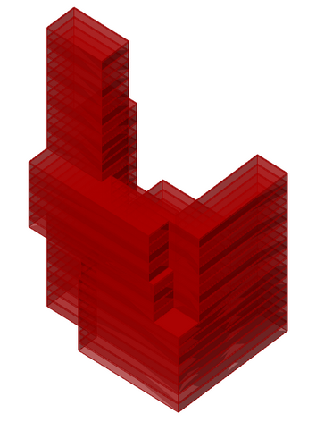
The spatial boundary defines the type of building massing to be generated, such as a high-rise tower or a mid-rise complex. Horizontally, it is defined by the column-grid counts and span sizes; vertically, it is defined by the number of floors and the floor height. You can also specify different span sizes in the two directions and a range of floor counts to increase design variability.
空间边界用于控制生成建筑的类型,例如高层塔楼或多层综合体。在该组件中,空间边界由进深、开间、层数、柱间距和层高共同控制。柱间距还可以在两个方向上分别设置,以提高形态灵活性。
 |  |  |
|---|---|---|
| | |
 |  |  |
| | |
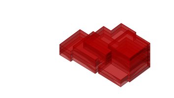
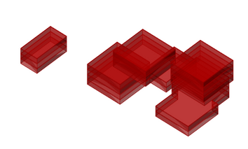
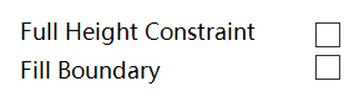
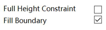
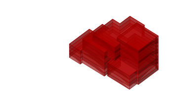
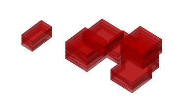
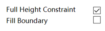
Because of its generative mechanism, the additive component cannot always guarantee that the generated volume reaches the specified footprint dimensions and floor count. To enforce the column-grid and floor-count targets, enable Full Height Constraint and Fill Boundary.
由于加法组件的生成机制,生成设计不一定能够占满整个预定义空间,例如可能在较大范围内生成较小的体量。如果希望设计占满生成范围,可以启用“Full Height Constraint”和“Fill Boundary”,以确保其在垂直和水平方向上达到目标范围。
 |  |
|---|---|
 |  |
 |  |
 |  |
3.1.2 Additive Unit Mass 叠加子体量
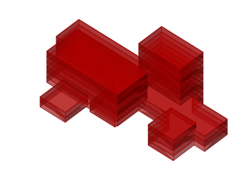
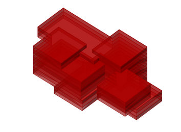
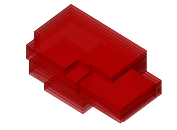
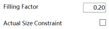
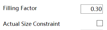
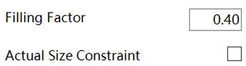
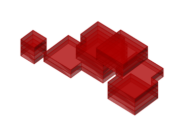
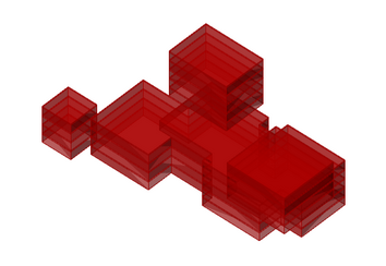
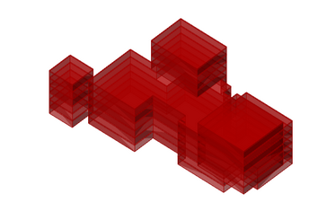
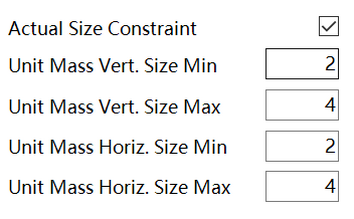
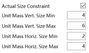
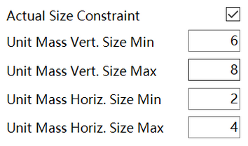
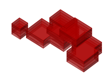
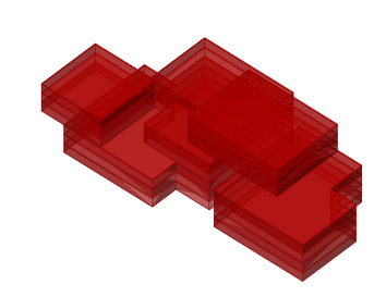
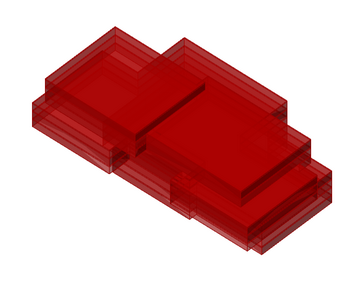
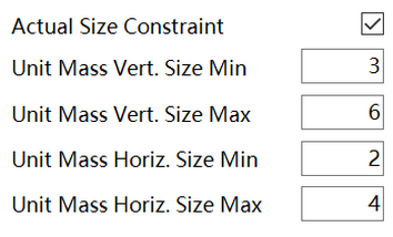
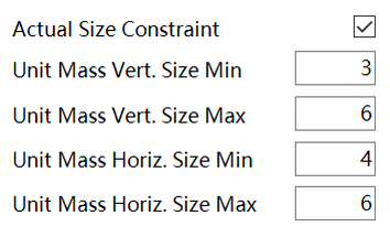
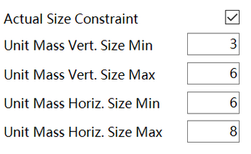
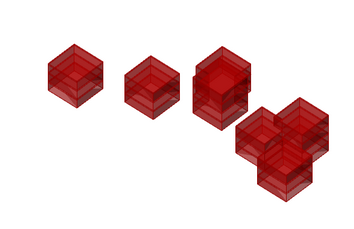
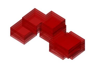
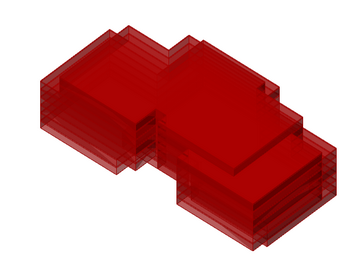
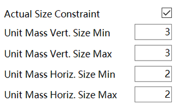
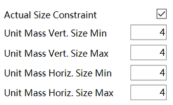
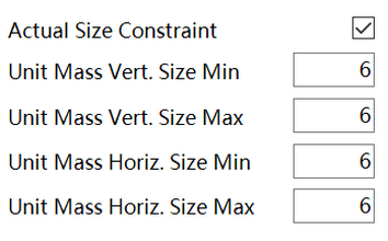
The additive component creates the building volume by aggregating unit masses. The number and size of the unit masses affect the complexity of the generated design. You can control the overall volume in two ways. Filling Factor specifies how much of the initial volume is filled and scales each unit mass accordingly. Actual Size Constraint specifies the actual size range of each unit mass. Setting the minimum and maximum to the same value produces rectangular unit masses.
加法组件通过叠加多个子体量生成建筑体量。子体量的数量和尺寸会影响生成设计的复杂度。总体形态可以通过两种方式控制:第一种是“Filling Factor”,即预定义空间中被建筑占据的大致比例,并据此整体缩放子体量;第二种是“Actual Size Constraint”,用于直接控制每个子体量的实际尺寸。将尺寸上下限设置为相同值,可以生成方形平面的子体量。
 |  |  |
|---|---|---|
 |  |  |
 |  |  |
 |  |  |
 |  |  |
 |  |  |
 |  |  |
 |  |  |
I
3.1.3 Generate Cores 生成核心筒
Same as the “Generate Cores” function in the subtractive component. Please refer to 2.1.4.
该部分内容请参考2.1.4
3.1.4 Target Gross Area 目标建筑面积
Same as the “Generate Cores” function in the subtractive component. Please refer to 2.1.5.
该部分内容请参考2.1.5
3.1.5 Façade Types 立面类型
Same as the “Generate Cores” function in the subtractive component. Please refer to 2.1.6.
该部分内容请参考2.1.6
3.2 Advanced setting 高级设定
In the advanced settings, these parameters allow you to create more complex building-massing designs or guide the generation process more precisely. They are optional and can usually be left at their default values.
高级设置包含用于生成更复杂体量形态、并对生成过程进行更精细控制的参数。一般情况下无需修改这些参数。
3.2.1 Interfering point 干扰点
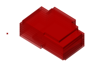
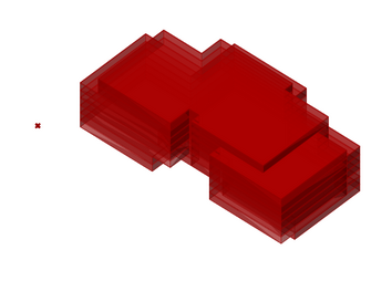
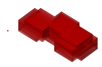
This function allows you to attract or repel unit masses relative to a point. For example, you can define an entrance area by attracting more unit masses toward it. Draw the point in Rhino, rather than Grasshopper, and pick it after clicking Set Point. Positive values indicate attraction; negative values indicate repulsion.
该功能允许设计师通过干扰点控制子体量的位置。例如,可以将子体量吸引到建筑的一侧或一角,以形成入口空间。使用该功能时,请先在Rhino中创建一个点,再单击“Set Point”进行拾取。正值表示吸引,负值表示排斥。
 |  |  |
|---|---|---|
| | |
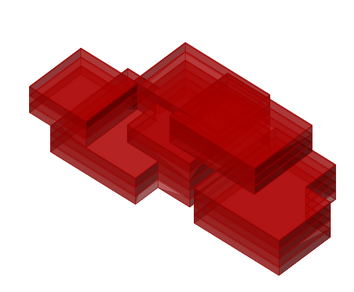
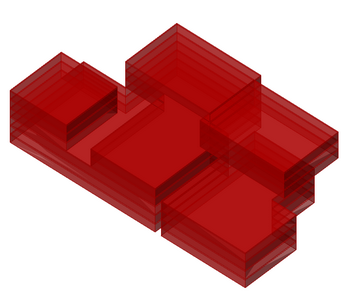
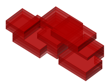
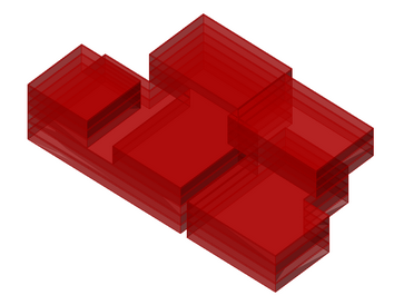
3.2.2 Separation Control 分离控制
This function controls the spacing between unit masses. When enabled, it keeps nearby unit masses farther apart in the horizontal and/or vertical directions. It has an effect only when two or more unit masses are close to one another.
该功能用于控制子体量之间的间距。启用后,彼此接近的子体量会在水平方向和/或垂直方向上保持更大的距离。
 |  |
|---|---|
| |
 |  |
| |
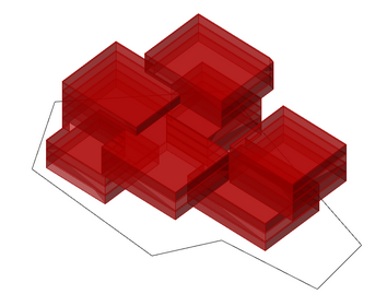
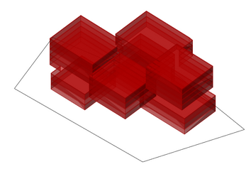
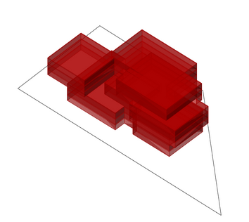
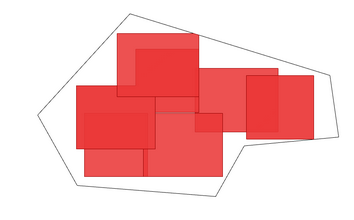
3.2.3 Custom Boundary 自定义边界
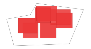
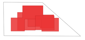
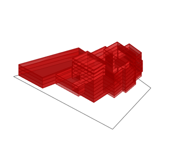
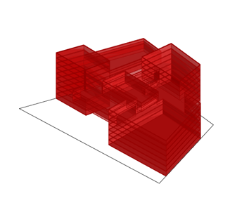
This function allows you to define a more complex building footprint by picking a closed polyline in Rhino. It provides the same two boundary modes as the subtractive component:
- Boundary Packing keeps the original rectangular grid and repositions the generated units so that they fit within the custom boundary.
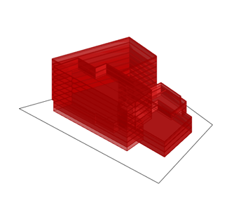
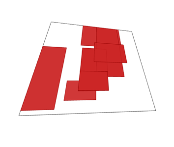
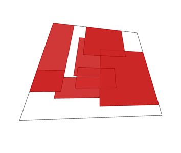
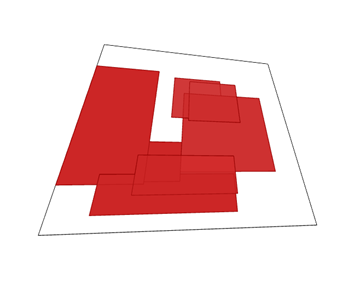
- Boundary Adaptation generates the massing on the rectangular working footprint and then maps it to the custom boundary. Use a closed quadrilateral with an area reasonably close to the original footprint; otherwise the boundary validation will reject it.
该功能允许设计师在 Rhino 中拾取闭合的多段线,以定义更复杂的建筑平面边界。它与减法组件提供相同的两种边界模式:
- 边界排布(Boundary Packing):保留原有矩形网格,并重新调整生成单元,使其适合放入自定义边界内。
- 边界适配(Boundary Adaptation):先在矩形工作边界内生成体量,再将体量映射到自定义边界。请使用闭合四边形,并确保其面积与原始工作边界相近,否则边界校验会拒绝该边界。
边界排布(Boundary Packing)
 |  |  |
|---|---|---|
 |  |  |
边界适配(Boundary Adaptation)
 |  |  |
|---|---|---|
 |  |  |
3.2.4 External Volume 外部体量
Same as the “External Volume” function in the subtractive component. Please refer to 2.2.4.
该部分内容请参考2.2.4
3.2.5 Vertical Constraint Check 垂直约束检查
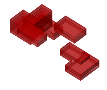
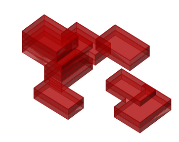
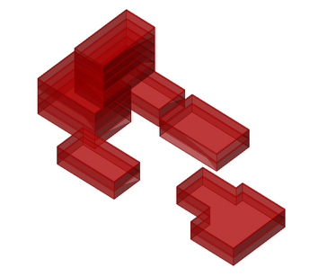
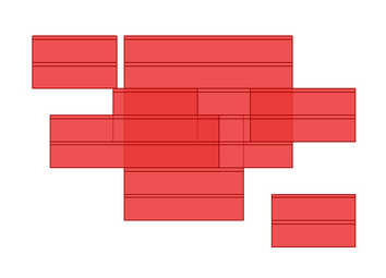
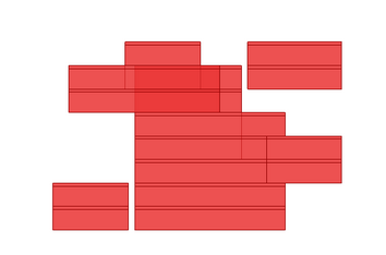
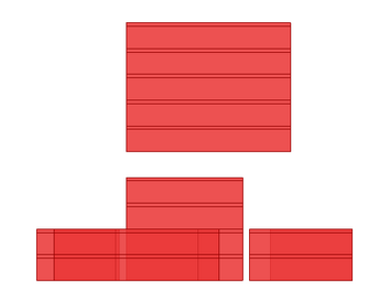
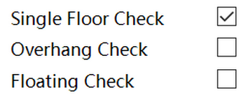
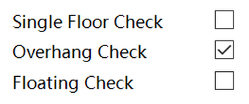
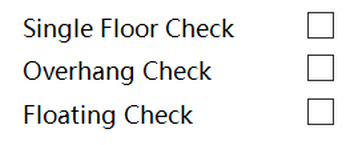
The additive component is more likely than the subtractive component to generate undesirable forms such as floating volumes. Three constraints are therefore enabled by default to reduce these cases. You can disable them when a degree of geometric infeasibility is acceptable.
加法组件的生成逻辑更容易产生悬浮体量等无效设计。因此,组件默认启用三个用于约束体量垂直位置的功能,以减少这类情况。当项目允许一定程度的几何不合理性时,也可以关闭这些约束。
 |  |  |
|---|---|---|
 |  |  |
 |  |  |
3.2.6 Fixed Void 固定负空间
Same as the “Fixed Void” function in the subtractive component. Please refer to 2.2.6.
该部分内容请参考2.2.6
3.2.7 Unit Masses Appearing Position 子体量位置约束
Same as the “Subtractor Appearing Position” function in the subtractive component. Please refer to 2.2.7.
该部分内容请参考2.2.7
3.3 Transformation 变换设定
Same as the “Transformation” tab in the subtractive component. Please refer to 2.3.
该部分内容请参考2.3
3.4 Generation settings 生成设定
Same as the “Generation settings” in the subtractive component. Please refer to 2.4.
该部分内容请参考2.3
4 Design Optimization 设计优化
To support automated design optimization, EvoMass provides a hybrid evolutionary algorithm called the Steady-State Island Evolutionary Algorithm (SSIEA). SSIEA divides the design population into subpopulations so that each can explore a distinct region of the search space, while its steady-state strategy supports efficient replacement. The component also provides workflow features such as automatic backups and screenshot capture.
为了支持自动化设计优化,EvoMass提供了混合进化算法SSIEA。该算法借助“多岛模型”和“稳态替换策略”将设计种群划分为多个子种群,使不同子种群探索设计空间中的不同区域,从而提高搜索的探索性。此外,优化组件还提供自动备份和截图等功能。
4.1 Input/Output 输入/输出
4.1.1 Connection 连接
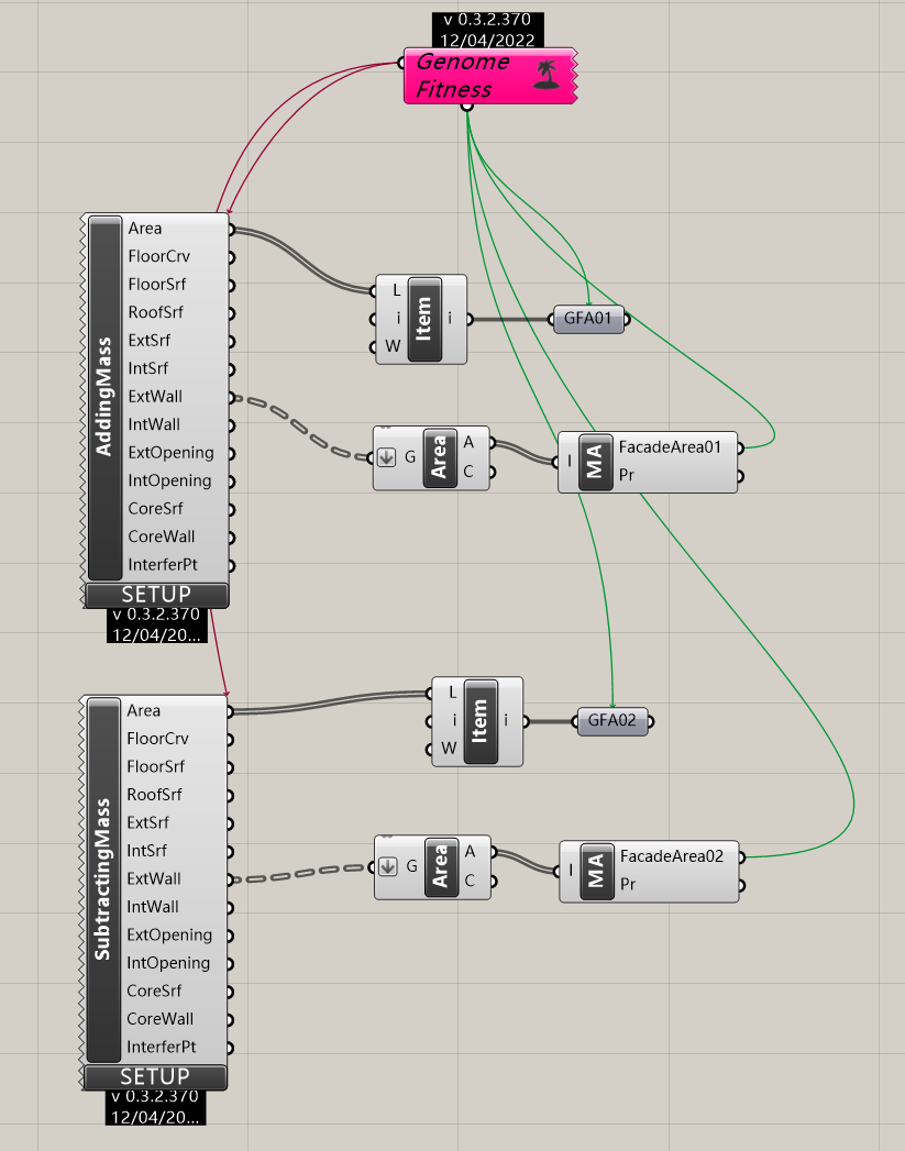
The SSIEA component allows you to connect multiple additive or subtractive generative components as outputs and evolve their parameters together. Connect each component output to the SSIEA output side, and connect scalar analysis results to the Value/Fitness inputs. Each connected output must provide one scalar value per design; lists and data trees are not supported. The input nickname becomes the recorded output name in the table, scatter plot, and parallel-coordinate chart, so use clear, stable names such as FitnessFloorArea or ValueRoofArea.
SSIEA组件允许在输出端连接多个加法或减法生成组件,并共同优化它们的参数。请将标量分析结果连接到Value/Fitness输入;每个设计只能提供一个标量,不能使用列表或数据树。输入端昵称会作为表格、散点图和平行坐标图中的输出名称,因此建议使用稳定、清晰的名称,例如“FitnessFloorArea”或“ValueRoofArea”。
4.1.2 Outputs 输出
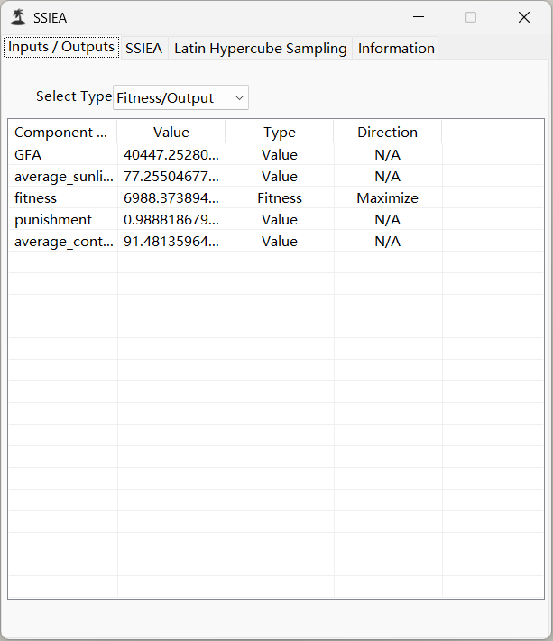
Once the inputs and outputs are connected, double-click the SSIEA component to open its editor. In the Outputs tab, classify each output as either Fitness or Value. Fitness outputs are optimization objectives and require a direction: Maximize or Minimize. Value outputs are recorded for analysis but do not influence selection. EvoMass supports one or two fitness outputs; all remaining outputs are recorded values. The output nickname shown in the first column becomes the label used by the data table and visualization axes. Do not rename an output while relying on an existing backup file, because the backup must match the original setup.
连接完毕后,双击SSIEA组件打开编辑器。在Outputs标签中,将每个输出分类为“Fitness”或“Value”。Fitness是优化目标,需要选择“Maximize”或“Minimize”;Value仅用于记录和分析,不参与选择。EvoMass支持一个或两个Fitness输出,其余输出均为Value。第一列显示的输出昵称会成为表格和图表的轴标签。使用已有备份文件时不要修改输出昵称或组件设置,否则备份可能无法匹配。
4.1.3 Inputs 输入
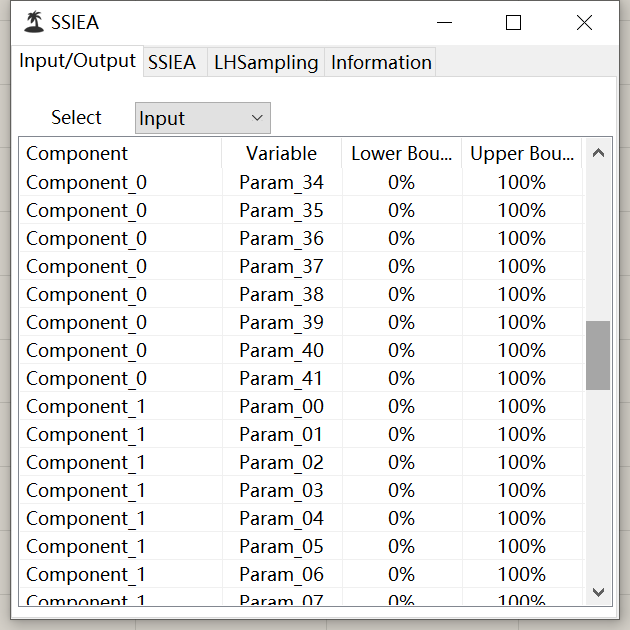
In this tab, you can change the viewer to show the information of the input. In the input viewer, you can see the parameter number of the component. If there are multiple generative components connected, you can also see the names of the connected components. In most cases, you don’t need to check this tab as no parameter needs to change here.
该选项卡用于查看所连接生成器所需的参数数量;如果连接了多个生成器,还可以查看其名称。在大多数情况下无需修改此处的内容。
4.2 SSIEA setting SSIEA算法设置
The second tab is the SSIEA settings panel. Use it to define the search behavior, initial-population strategy, screenshot capture, and backup/restart options.
第二个选项卡用于设置SSIEA算法参数,这些参数会影响优化过程的搜索行为。
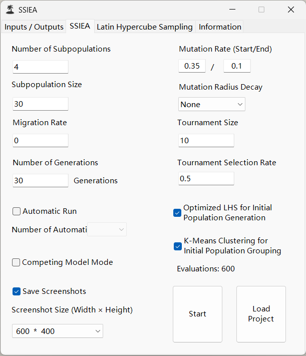
Because SSIEA uses an island-based approach, its population settings differ slightly from those of other evolutionary algorithms. Define the number of subpopulations and the subpopulation size. The total population size is their product. When multiple subpopulations are used, SSIEA can migrate designs between them after a subpopulation converges. Use the migration rate to control the likelihood of migration. High migration rates may reduce diversity because high-fitness designs from one subpopulation can replace strong designs in another. The remaining parameters are described below.
由于采用“多岛模型”,SSIEA的种群设置与常见进化算法略有不同。使用SSIEA时,需要设置子种群数量和子种群大小;设计种群总数等于两者的乘积。当存在多个子种群时,某个子种群收敛后,SSIEA可以将设计个体迁移到其他子种群。可以通过“Migration Rate”控制迁移概率。迁移率过高可能降低优化结果的多样性,因为一个子种群中的高适应度设计可能迅速替换另一个子种群中的优秀设计。下表概述了主要参数的含义。
| Parameter 参数 | Meaning 含义 | Typical Value 典型值 |
|---|---|---|
| Number of Generations 代数 | The number of generations. The UI also reports the resulting evaluation count. Very large values may reduce diversity and increase run time. 进化代数;界面会同时显示由设置计算出的评价次数。过大的数值可能降低多样性并增加运行时间。 | 10-100 |
| Mutation Rate (Start/End) 变异率(起始/结束) | The mutation probability at the beginning and end of the run. Lower values are more exploitative; higher values are more exploratory, but excessive mutation approaches random search. 优化开始和结束时的变异概率。较低数值偏向挖掘,较高数值偏向探索,但过高会趋近随机搜索。 | 0.1-0.5 |
| Mutation Radius Decay 变异半径衰减 | Controls how the mutation radius decreases during the run, making the search more exploratory at first and more focused later. 控制优化过程中变异半径的递减,使前期更偏向探索、后期更偏向局部搜索。 | - |
| Tournament Size 竞争集大小 | The number of candidates selected from each subpopulation for tournament selection. 每代从子种群中选入竞争选择的候选个体数量。 | 30–50% of the subpopulation size 子种群大小的30–50% |
| Tournament Selection Rate 竞争选择率 | The proportion of tournament candidates selected for reproduction. 从竞争集中选择用于繁殖的个体比例。 | 0.5 |
| Optimized LHS for Initial Population Generation 用于初始种群生成的优化拉丁超立方 | Creates an optimized Latin-hypercube sample before SSIEA starts, giving the initial designs a more even distribution across the parameter space. This is separate from the main SSIEA run. 在SSIEA开始前生成更均匀分布的初始设计;该过程独立于SSIEA主优化过程。 | - |
| K-Means Clustering for Initial Population Grouping 用于初始种群分组的K均值聚类 | Groups the initial designs into the configured number of subpopulations, with equal subpopulation sizes, so each subpopulation starts from a different region of the design space. This option is disabled for competing model mode and when only one subpopulation is used. 将初始设计按设定的子种群数量和大小进行等量分组,使不同子种群从设计空间的不同区域开始搜索。竞争模型模式以及只有一个子种群时不使用该选项。 | - |
| Competing Model Mode 竞争模型模式 | Compares two different parametric models. Because the models can describe different design spaces, K-Means grouping is not applied across them. 用于比较两个不同的参数化模型;由于两个模型可能对应不同的设计空间,不在模型之间执行K均值分组。 | - |
| Evaluations 评价次数 | The estimated number of design evaluations from the current settings. It is useful for planning run time, but the actual elapsed time depends on the connected components and analysis tools. 根据当前设置估算的设计评价次数;实际耗时还取决于连接的组件和分析工具。 | - |
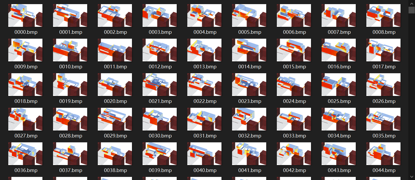
| Save Screenshots / Screenshot Size 保存截图/截图尺寸 | Captures the active Rhino view for evaluated designs and stores the images in the run backup folder. Set the Rhino view before starting. Screenshots enable previews in the table and interactive plot annotations; without screenshots, annotations still show text but no image preview. 对评价设计的当前Rhino视图进行截图并保存到本次运行的备份文件夹。开始优化前请先调整Rhino视图。截图可用于表格和交互式图表中的预览;未启用截图时仍显示文字标注,但不会显示图片。 | - |
Once all parameters are defined, click Start to launch the optimization. EvoMass automatically creates a backup folder containing the GH file, optimization data, component settings, and, when enabled, screenshots. Existing backup files may be overwritten, so use a new project folder for each run.
完成参数设置后单击“Start”开始优化。EvoMass会在当前文件夹创建备份目录,其中包括GH文件、优化数据、组件设置以及(启用后)截图。已有备份可能被覆盖,因此建议每次运行使用新的项目文件夹。
4.3 Optimization Viewer 优化窗口
4.3.1 Main Viewer 主窗口
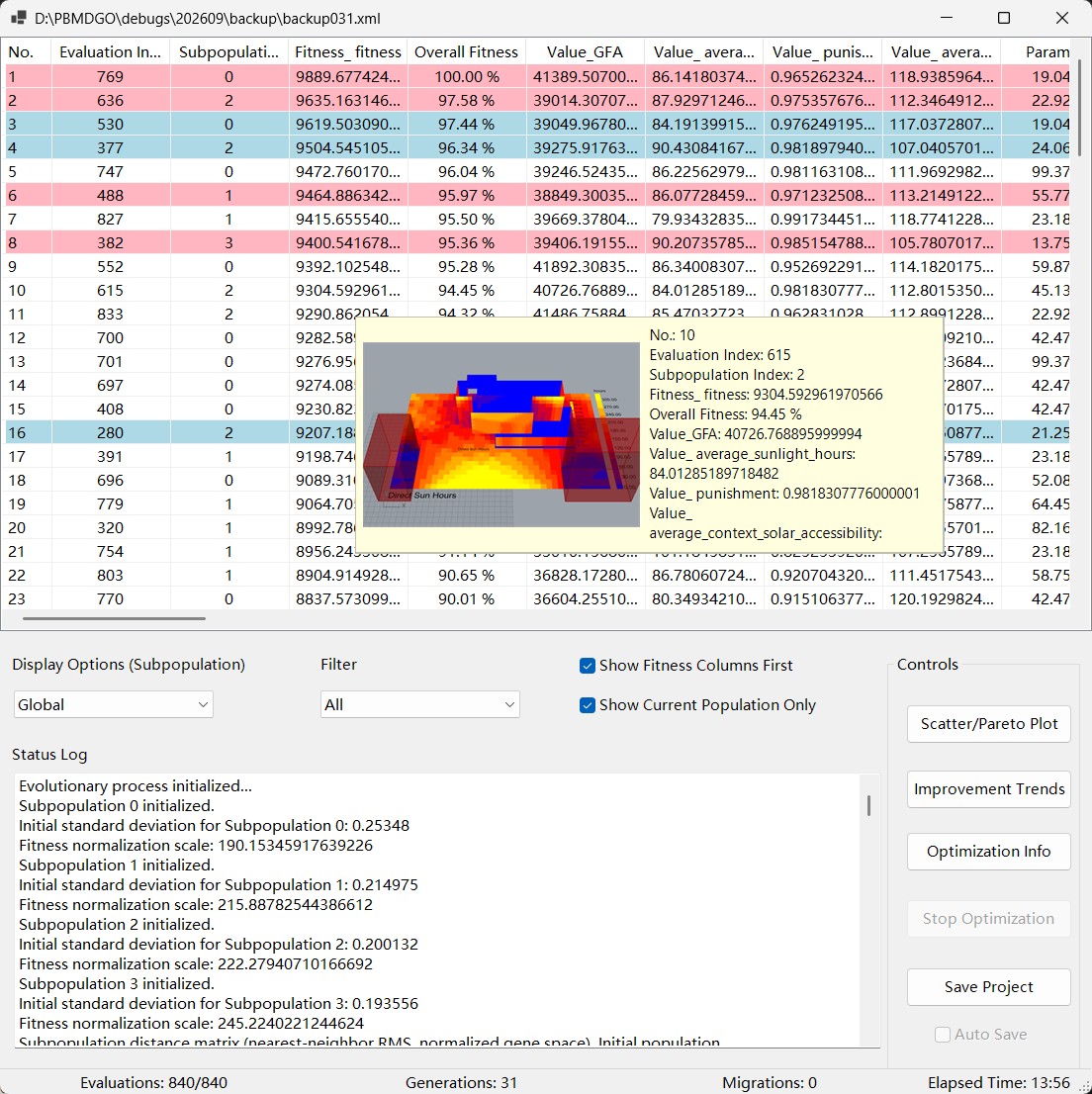
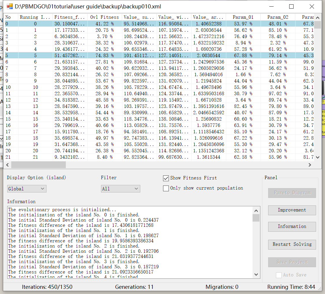
Once an optimization starts, the Evolutionary Optimization viewer opens. It reports evaluations, generations, migrations, elapsed time, and the current status. The table lists evaluated designs, their fitness outputs, recorded values, parameters, subpopulation, and evaluation index. Hovering a row shows a screenshot preview when Save Screenshots was enabled. The display selector can show the global population or one subpopulation. The filter can show all designs, improvement designs, the Pareto front, or both. Show Current Population Only hides designs that have been replaced. Right-click a design row to generate that model in Grasshopper, export CSV, or copy its data.
优化开始后会打开Evolutionary Optimization窗口,显示评价次数、代数、迁移次数、运行时间和当前状态。表格列出设计、Fitness、Value、参数、子种群和评价编号。启用“Save Screenshots”后,将鼠标悬停在表格行上可以查看截图预览。Display selector可选择Global或某个子种群,Filter可选择全部、改进解、帕累托前沿或两者。勾选“Show Current Population Only”可隐藏已被替换的设计。右键单击设计行可以在Grasshopper中生成模型、导出CSV或复制数据。
4.3.2 Scatter/Pareto Plot 散点/帕累托图
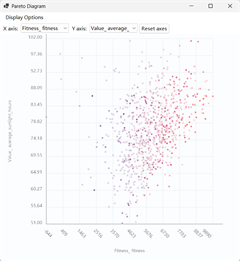
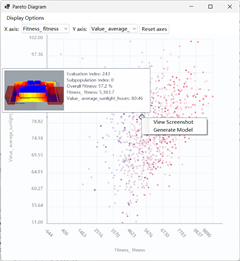
Click Scatter/Pareto Plot when the optimization has more than one output. The plot can map any two different outputs to the X and Y axes, including fitness outputs and recorded values. Output names come from the nicknames defined in the SSIEA Outputs tab. If the two selected axes are the two fitness objectives, the Pareto front can be displayed; if either axis is a recorded value, the chart remains a general scatter plot and no Pareto front is drawn. The axis selectors prevent choosing the same output for both axes, and Reset axes returns to the initial selection (both fitness outputs when two exist, otherwise the first available value is used for the Y axis).
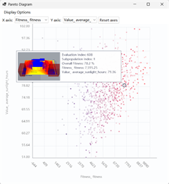
All evaluated designs are shown as age-faded points: newer designs use stronger colors and older designs use lighter colors. The Pareto front is drawn with an emphasized orange line and points when available. Hover a point after the optimization is stopped or completed to highlight it and show its design annotation. If screenshots were saved, the annotation includes a preview; left-click opens the larger screenshot viewer and right-click provides Generate Model.
当优化输出多于一个时,单击“Scatter/Pareto Plot”打开散点图。图表可以将任意两个不同的输出映射到X轴和Y轴,包括Fitness输出和记录的Value。输出名称来自SSIEA Outputs选项卡中设置的昵称。当两个坐标轴均选择Fitness目标时,图表可以显示帕累托前沿;如果任一坐标轴选择Value,图表仅作为普通散点图,不显示帕累托前沿。坐标轴选择器不允许为两个坐标轴选择相同的输出;“Reset axes”会恢复初始选择(存在两个Fitness时默认选择这两个Fitness,否则Y轴默认选择第一个可用的Value)。
所有已评价设计都会以随时间淡化的颜色显示:较新的设计颜色更深,较早的设计颜色更浅。可用时,帕累托前沿会以更醒目的橙色线和点显示。优化停止或完成后,将鼠标悬停在点上可高亮该点并显示设计标注。若已保存截图,标注中会包含预览;左键单击可打开较大的截图查看器,右键单击可使用“Generate Model”。
 |  |  |
|---|---|---|
| Default view 默认视图 | Hover over a design point 悬停在设计点上 | Left-click the design point 左键单击设计点 |
4.3.3 Improvement Viewer 改进解窗口
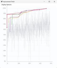
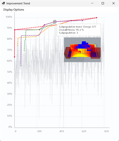
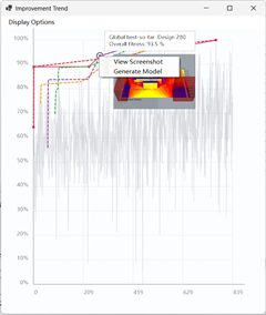
Click Improvement Trends to open the improvement-design chart. It shows the emergence of the best designs found during the run; points represent designs and colors indicate their subpopulation. When the optimization is stopped or completed, hover over a point to highlight it and show its annotation. If screenshots were saved, the annotation includes the design image; left-click opens the image viewer and right-click offers Generate Model. These interactions are intentionally disabled while the optimization is running to avoid interfering with live updates. The display options can switch between global and subpopulation trends, and between current and original subpopulation assignments.
单击“Improvement Trends”打开改进趋势图。点表示优化过程中出现的改进设计,颜色表示子种群。优化停止或完成后,将鼠标悬停在点上可高亮设计并显示标注;如果保存了截图,标注中还会包含图片。左键单击可打开较大的图片查看器,右键单击可使用“Generate Model”。优化运行时禁用这些交互,以避免干扰实时更新。
 |  |  |
|---|---|---|
| Default view 默认视图 | Hover over a design point 悬停在设计点上 | Left-click the design point 左键单击设计点 |
4.3.4 Information Viewer 信息窗口
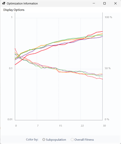
Click Optimization Info to open the information viewer. The progression chart shows normalized overall-fitness trends and standard-deviation trends for each subpopulation. Solid lines represent normalized average overall fitness; dashed lines represent within-subpopulation standard deviation. During optimization, these curves update as generations finish. When the run is stopped or completed, hover a point for an annotation; saved screenshots are included when available, and the same left-click image viewer/right-click Generate Model actions are available.
单击“Optimization Info”打开信息窗口。进度图显示各子种群的归一化Overall Fitness趋势和标准差趋势:实线表示归一化平均Overall Fitness,虚线表示子种群内部的Fitness标准差。优化停止或完成后,将鼠标悬停在点上可显示标注,并可使用截图查看和“Generate Model”功能。
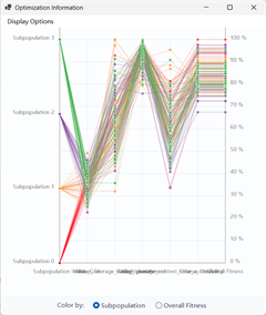
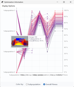
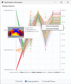
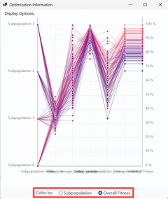
Switch the display to Parallel Coordinates to inspect each evaluated design across its subpopulation index, fitness outputs, recorded values, and generation parameters. Hovering a line highlights the nearest design line and places its annotation at the mouse position. The annotation identifies the design, subpopulation, and overall fitness, and includes a screenshot when one was saved. The interaction is available only after the optimization is stopped or completed.
切换到“Parallel Coordinates”可查看每个设计的子种群编号、Fitness、Value和生成参数分布。鼠标悬停在线上时,距离鼠标最近的设计线会高亮,标注会显示在鼠标位置。优化停止或完成后才启用此交互。
 |  |  |
|---|---|---|
| Default view 默认视图 | Hover over a design line 悬停在设计线上 | Left-click the design line 左键单击设计线 |
The parallel-coordinate display can show all outputs and parameters or only fitness/value outputs. Use the bottom Color by controls to sort line colors by Subpopulation or Overall Fitness; this is more visible than a hidden context-menu command. The gradient uses the current purple-blue/pink fitness scheme, while subpopulation colors remain distinct on a white background. Right-clicking a highlighted line offers View Screenshot and Generate Model when the run is not active.
在“Display Options”中,可以只显示Fitness和Value,隐藏生成参数。画布底部的“Color by”控件可选择按“Subpopulation”或“Overall Fitness”设置颜色。右键单击高亮线可选择“View Screenshot”和“Generate Model”。
4.4 Data Backup 数据备份
When the optimization is running, EvoMass maintains a backup folder containing the GH file, optimization data, component settings, and generation records. Backup files can be overwritten by a later run, so keep separate project folders when you need to preserve multiple runs.
优化开始后,EvoMass会在GH文件所在文件夹维护备份目录,用于保存GH文件、优化数据、组件设置和运行记录。后续运行可能覆盖旧备份,因此需要保留多个运行记录时,请使用不同的项目文件夹。

This folder contains XML files named backupXXX.xml. A file is created at the end of each generation, and the final file corresponds to the latest completed generation. If the optimization is stopped or interrupted, you can use the latest backup to restart it.
备份文件夹中包含一系列名为BackupXXX.xml的文件。这些文件会在每代结束时自动创建,最后一个文件对应最近完成的代数。因此,如果优化过程意外中断,可以使用最新的备份恢复优化。
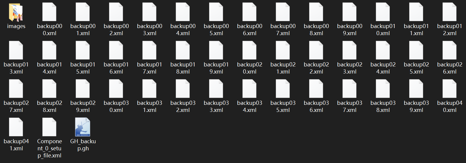
If you accidentally change the original GH file, use the backup copy in this folder. The XML can only be loaded when the EvoMass components, output nicknames, and value/fitness components still match the original setup. The images folder contains screenshots captured during the run and is created only when Save Screenshots is enabled.
如果不慎修改了原有GH文件,可以使用备份目录中的副本。只有当EvoMass组件、输出昵称以及Value/Fitness组件仍与原始设置一致时,才能读取XML文件。images文件夹用于保存运行截图,仅在启用“Save Screenshots”时创建。
4.5 Restart/Load Optimization 重新开始/载入优化
If the computer crashes, you stop the run, or you want to analyze results later, load the latest XML from the backup folder. Click Load Project in the SSIEA editor and select the XML; EvoMass restores the saved population, settings, records, and elapsed time.
如果电脑崩溃、需要停止运行,或希望稍后分析结果,可以从备份目录加载最新的XML。在SSIEA编辑器中单击“Load Project”并选择XML,EvoMass会恢复种群、设置、记录和累计运行时间。
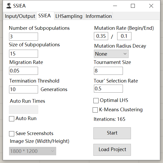
If the loaded optimization is not finished, click Restart Optimization once the main viewer pops up. The elapsed optimization time is restored from the project data and continues accumulating across stop/restart sessions; it is not reset to only the duration of the most recent session.
如果载入的优化尚未完成,请在主窗口出现后单击“Restart Optimization”继续优化。已用时间会从项目数据中恢复,并在暂停和重新开始之间继续累计,而不会只显示最近一次运行的时长。
5 Building Layout 建筑布局
The Layout Component supports urban-scale massing generation and optimization. It connects one or more additive/subtractive building-massing components and arranges their instances inside a user-defined site boundary. Layout parameters can be optimized together with the connected massing parameters, allowing the study of both building form and collective arrangement.
Layout Component用于支持城市尺度的体量生成和优化。它可以连接一个或多个加法/减法建筑体量生成组件,并在用户指定的用地边界内布置这些体量。布局参数可以与建筑体量参数一起被优化,从而同时研究建筑形态和建筑群布局对建成环境的影响。
5.1 Connection 连接
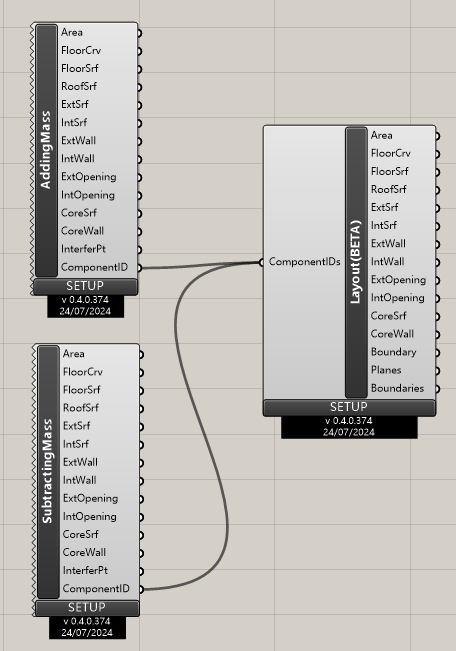
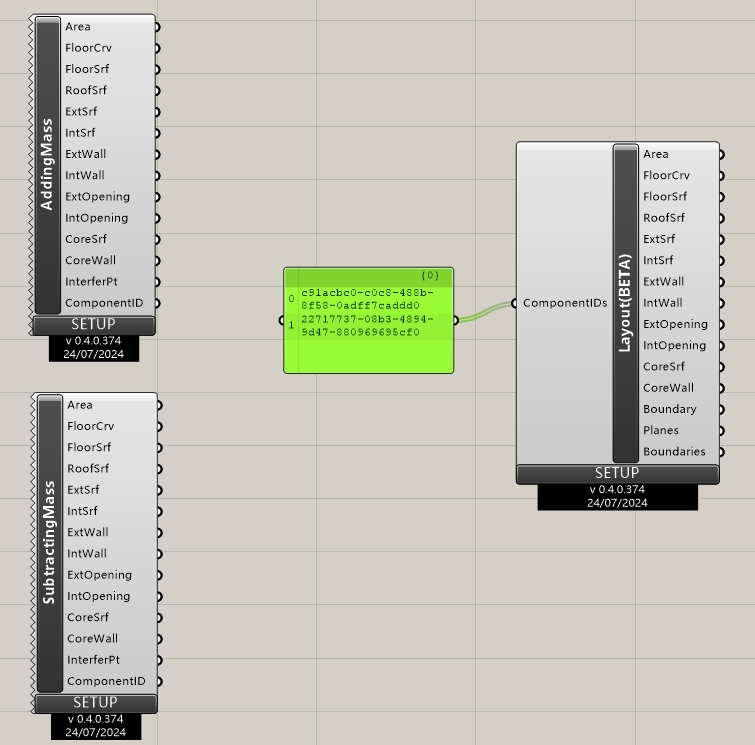
The Layout Component accepts a list of component instance IDs through ComponentIDs. The recommended workflow is to copy the generative component’s Component Instance GUID, paste it into a Panel, and connect the Panel to the Layout Component. A GUID may be repeated when the same generated massing should appear several times in the layout. IDs are validated before calculation; invalid, missing, or non-massing IDs produce a warning and leave the previous valid layout unchanged. Keep the number of connected instances reasonable because every additional layout instance increases the search dimension.
布局组件通过“ComponentIDs”接收生成组件实例ID列表。推荐右键点击生成组件,复制“Component Instance GUID”,将其粘贴到Panel,再把Panel连接到布局组件。同一个GUID可以重复使用,以便在布局中放置多个相同体量。组件会在计算前验证GUID;无效、找不到对象或对象不是体量生成组件时会发出警告,并保留之前有效的布局结果。由于每个布局实例都会增加搜索维度,应控制连接实例的数量。
 |  |
|---|
5.2 Generation 生成
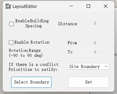
Double-click the component to open the Layout Editor. Select a valid, closed, planar Site Boundary, then configure optional building separation, rotation, collision priority, output grouping, and scaling. Click Apply Parameters to generate a layout. The boundary must have enough space for all connected massings; if placement or collision resolution fails, the component reports the error and preserves the previous valid output instead of replacing it with partial geometry.
双击组件打开“Layout Editor”。选择有效、闭合且平面的“Site Boundary”,然后设置可选的建筑分离、旋转、冲突优先级、输出分组和缩放参数。单击“Apply Parameters”生成布局。边界必须有足够空间容纳全部体量;如果放置或冲突处理失败,组件会报告错误并保留之前有效的输出,不会用不完整的几何替换它。
5.2.1 Building Separation 建筑分离
Enable Building Separation to request a minimum separation distance between building footprints. Separation and boundary constraints can conflict, so choose which constraint has priority in the editor.
启用“Building Separation”后,组件会尝试使建筑轮廓之间满足最小分离距离。分离约束和边界约束可能发生冲突,可在编辑器中选择优先满足的约束。
5.2.2 Rotation 建筑旋转
Enable Rotation to vary orientations between the specified From and To angles, in degrees. Enter the same value in both fields to use a fixed non-zero orientation. The accepted range is -90 to 90 degrees.
启用“Rotation”后,组件会在“From”和“To”角度之间改变建筑朝向,角度单位为度。若希望固定使用非零朝向,可在两个输入框中填写相同数值。允许的范围是 -90 至 90 度。
5.2.3 Conflict Resolution 冲突处理
When boundary containment and building separation cannot both be satisfied, use Collision Priority to choose the preferred constraint: prioritize the site boundary to keep all footprints inside the site, or prioritize building separation to maintain the requested spacing where possible.
当边界包含约束和建筑分离约束无法同时满足时,可使用“Collision Priority”选择优先约束:优先边界可确保所有轮廓位于用地内,优先建筑分离则尽可能保持指定间距。
5.3 Optimization 优化
For design optimization, connect the Layout Component to SSIEA. SSIEA recognizes the layout component and assigns the required number of parameters for generation and optimization. To optimize building massing at the same time, connect the corresponding generative components to SSIEA as well.
完成生成设置后,可以将布局组件与SSIEA优化算法组件相连接,SSIEA组件能够自动识别布局组件所需要的参数数量,并自动控制布局组件的参数调整和设计生成。你也可以同时将SSIEA组件与其他建筑布局组件相连接,实现建筑体量与布局的协同优化。